AutoMagicCalib#
Overview#
Auto Magic Calib main user interface#
Auto Magic Calib Microservice enables automatic calibration of multi-camera systems through a simple, web-based, step-by-step workflow.
It is powered by AutoMagicCalib (AMC), which estimates camera intrinsics and extrinsics to generate accurate projection matrices and lens distortion parameters for 3D and multi-view applications.
Unlike checkerboard-based methods, AMC uses naturally moving objects in the scene. With NVIDIA DeepStream detection and tracking, it follows objects (e.g., people) and derives camera parameters from normal operational footage—no setup, no downtime, and supports calibration from archived videos.
The service supports both a geometry-based approach (AMC) using object trajectories and geometric relationships, and a model-based approach (VGGT) that leverages learned models for higher accuracy and robustness.
Note
This document describes the Auto Magic Calib Microservice and UI. For standalone usage, detailed options, and advanced usage, see the AutoMagicCalib GitHub Repository.
Key Features#
Guided Workflow: 6-step process with progress tracking and real-time validation at each step
Project Management: Create and manage multiple projects; track states (INIT, READY, RUNNING, COMPLETED, ERROR); data persistence
Interactive Tools: ROI drawing on video frames, tripwire configuration, manual alignment (camera-to-world), real-time preview
Dual Calibration Methods: AMC (primary) and optional VGGT (Vision-Geometry Graph Transformer)
Export Options: Multiple formats, MV3DT-compatible export, full calibration with ROI/tripwire world coordinates and camera parameters
The calibration process follows: Project Setup → Video Configuration → Parameters → Manual Alignment → Execute → Results. Each step validates inputs before allowing progression to the next.
System Requirements#
x86_64 system
OS Ubuntu 24.04
NVIDIA GPU with hardware encoder (NVENC)
NVIDIA driver 590
NVIDIA container toolkit
Required for calibration
Camera video files (MP4 format) with moving objects for tracking, with sequential cameras having overlapping views.
Layout/map image (PNG format)
Optional
Ground truth data (ZIP file) for calibration evaluation
Pre-existing alignment data (JSON file)
Focal length values for cameras
Config parameters for your dataset
Quick Start#
Deploy the UI and backend microservice using Docker Compose.
NGC Setup#
This step is needed to pull AutoMagicCalib docker image.
Visit NGC sign in page, enter your email address and click Next, or Create an Account
Choose your Organization/Team
Generate an API key following the instructions
Log in to the NGC docker registry:
docker login nvcr.io
Username: "$oauthtoken"
Password: "YOUR_NGC_API_KEY"
Project Setup#
Clone the repo to your local directory.
git clone https://github.com/NVIDIA-AI-IOT/auto-magic-calib.git
cd auto-magic-calib
Configure Environment Variables#
Edit the compose/.env file to set the required environment variables.
Variable |
Required |
Default |
Description |
|---|---|---|---|
|
Yes |
— |
IP address of the host machine |
|
No |
|
Port for the microservice API |
|
No |
|
Port for the web UI |
|
No |
|
Path to the projects directory (can be modified to absolute path to your projects directory) |
|
No |
|
Path to the models directory (can be modified to absolute path to your models directory) |
# At minimum, set HOST_IP in compose/.env
HOST_IP=<your_host_ip>
Set Directory Permissions#
The projects and models directories must be owned by UID/GID 1000 for the containers to read/write properly.
chown 1000:1000 -R projects
chown 1000:1000 -R models
Launch Services#
Start all services using Docker Compose. Docker images will be pulled automatically on the first run.
cd compose
docker compose up -d
The microservice will be available at http://<HOST_IP>:<AUTO_MAGIC_CALIB_MS_PORT> (default port 8000) and the UI at http://<HOST_IP>:<AUTO_MAGIC_CALIB_UI_PORT> (default port 5000).
Note
To stop: docker compose down.
For VGGT, download the model from HuggingFace (e.g. VGGT-1B-Commercial) and place vggt_1B_commercial.pt in the models directory.
Workflow Steps#
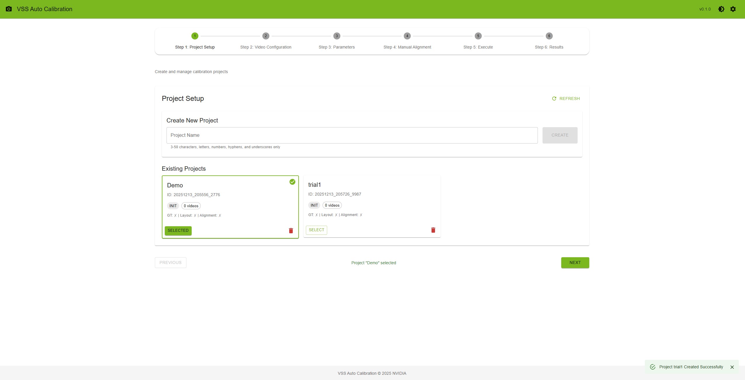
Step 1: Project Setup — Create a project (name 3–50 characters), click “Create”, then “Select”. Project cards show state, video count, and file status (GT, Layout, Alignment). Refresh or delete projects as needed.
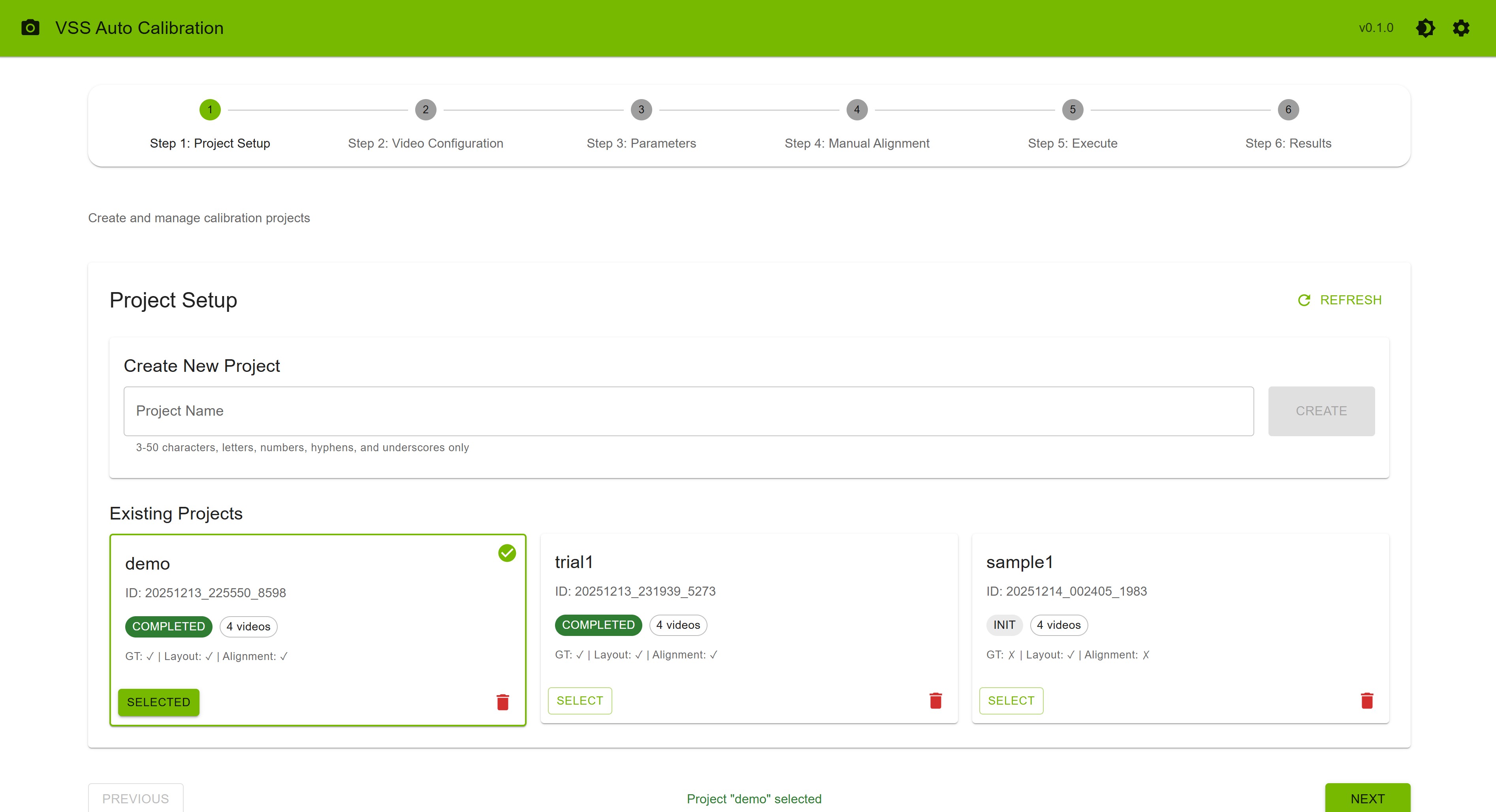
Project Setup Step#
Step 2: Video Configuration — Upload videos (e.g. MP4, 1920x1080) and a layout image. Optional: ground truth (ZIP), alignment (JSON). Order videos (cam_00, cam_01, …); consecutive cameras should have overlapping FOV.
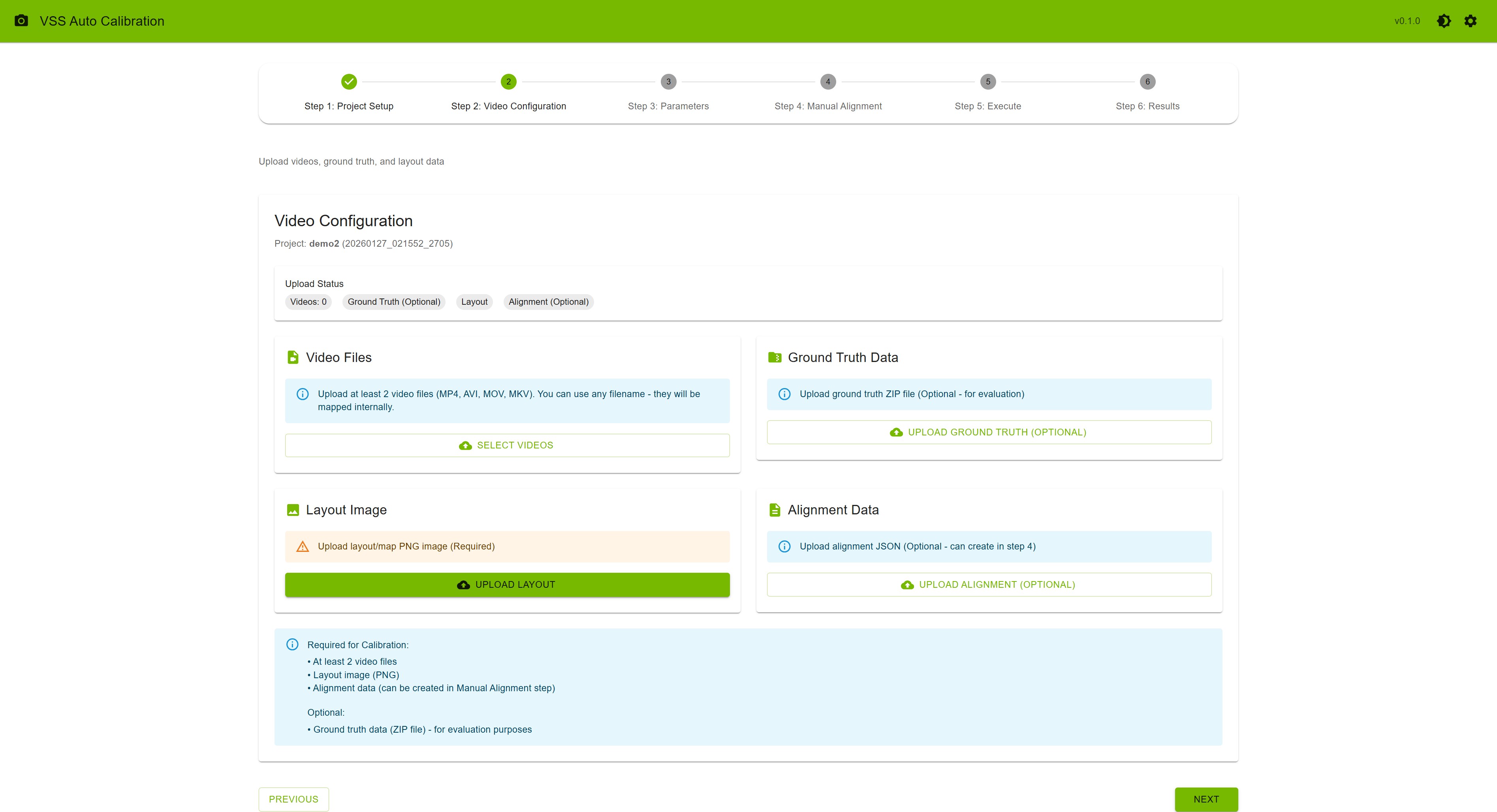
Video Configuration Step#
Step 3: Parameters — Select a camera; draw ROIs (polygon, min 3 points; press F to finish) and tripwires/directions. Set optional focal lengths (comma-separated). Use the settings icon on this step to upload config or adjust parameters.
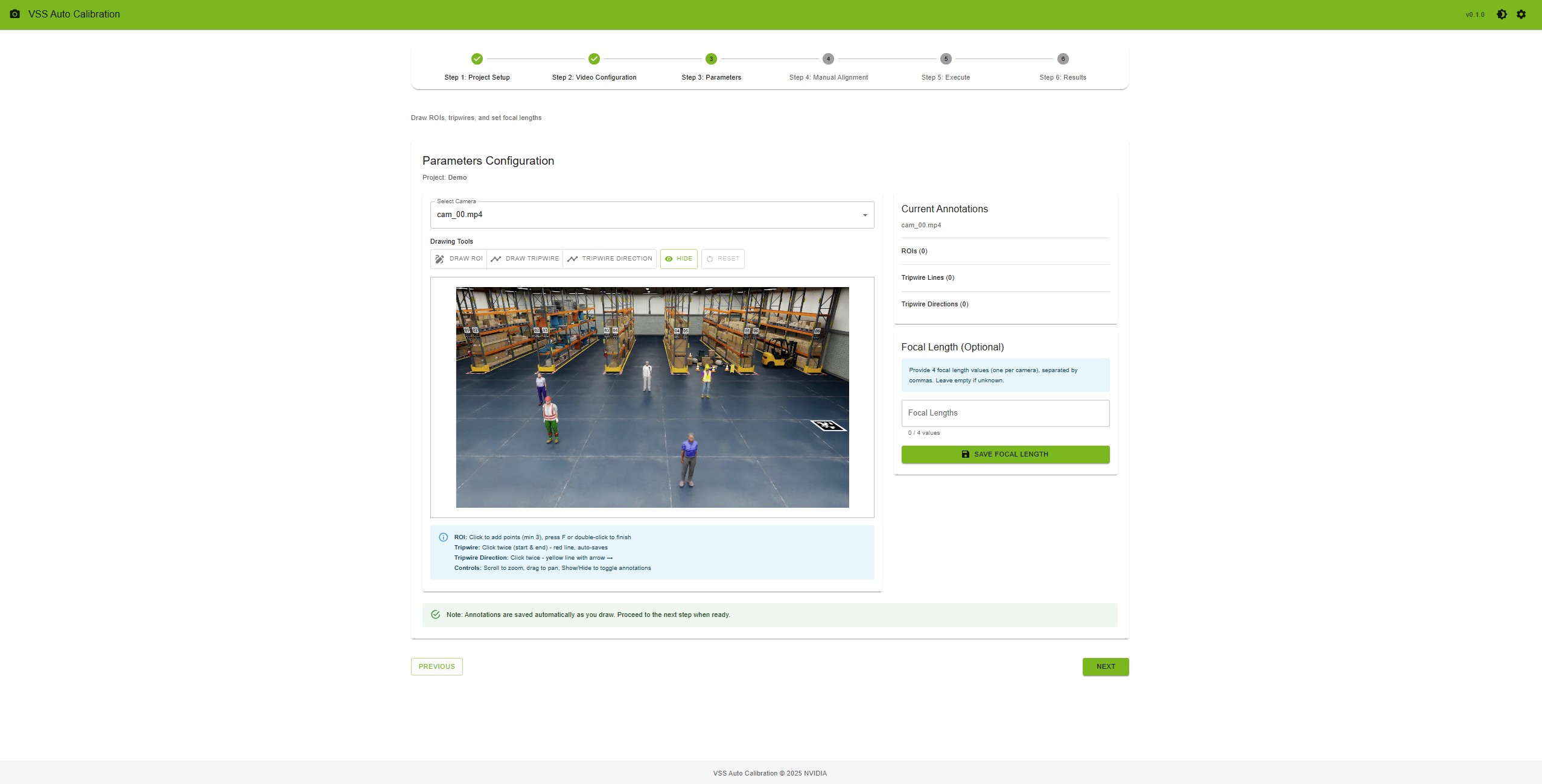
Parameters Step#
Step 4: Manual Alignment — Upload alignment_data.json (2A) or open the alignment tool (2B). Click the same physical point on Camera 0, Camera 1, and the layout map for each of at least 4 point sets; then “Save Alignment”.
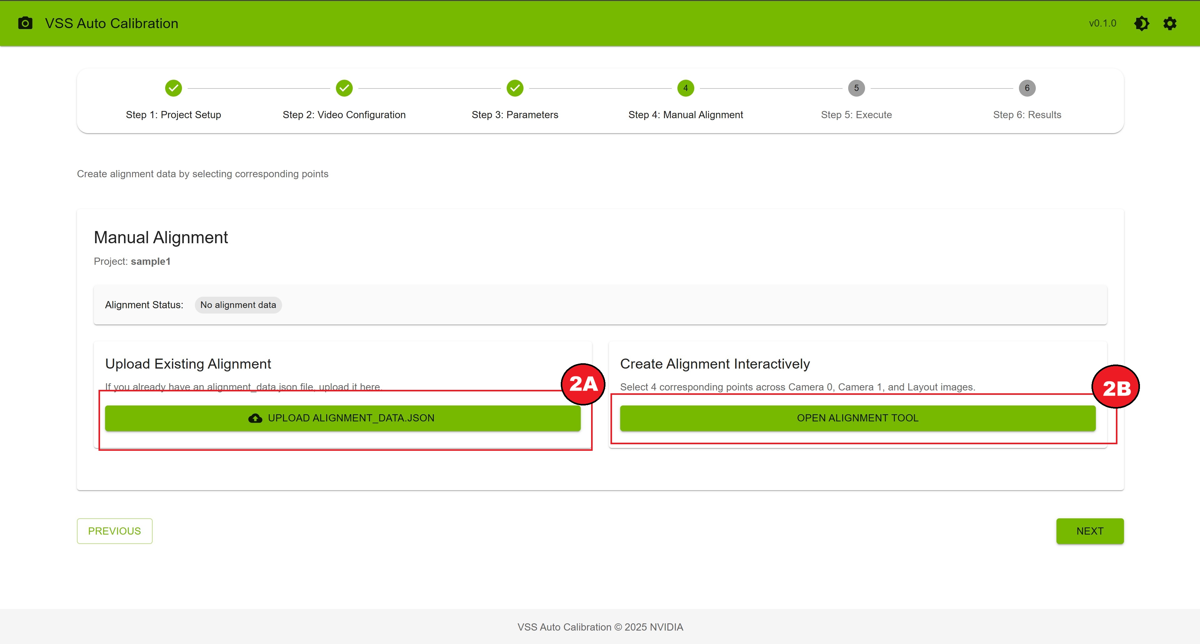
Manual Alignment Step#
If you want to create the alignment data interactively, you can use the alignment tool.
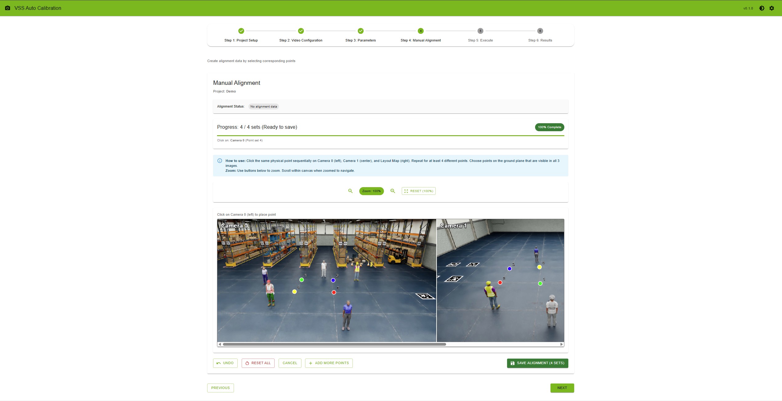
Manual Alignment Tool#
Step 5: Execute — Ensure requirements are met, click “Verify Project”, then “Start Calibration”. Monitor progress; optionally run VGGT after AMC completes. On failure, use “Relaunch Calibration” or “Reset Project”.
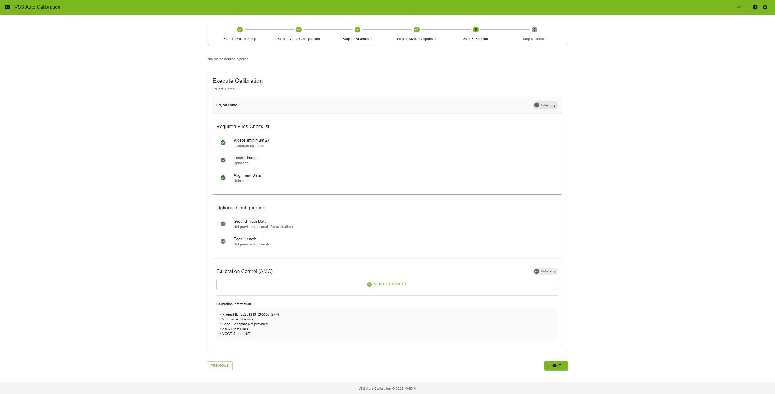
Execute Calibration#
Step 6: Results — View overlay image, evaluation metrics (if ground truth was uploaded), and per-camera parameters. Export via “Full Export AMC”/”Full Export VGGT” or “MV3DT ZIP AMC”/”MV3DT ZIP VGGT”. Use “Show ROI & Tripwire Verification” after full export to check projections.
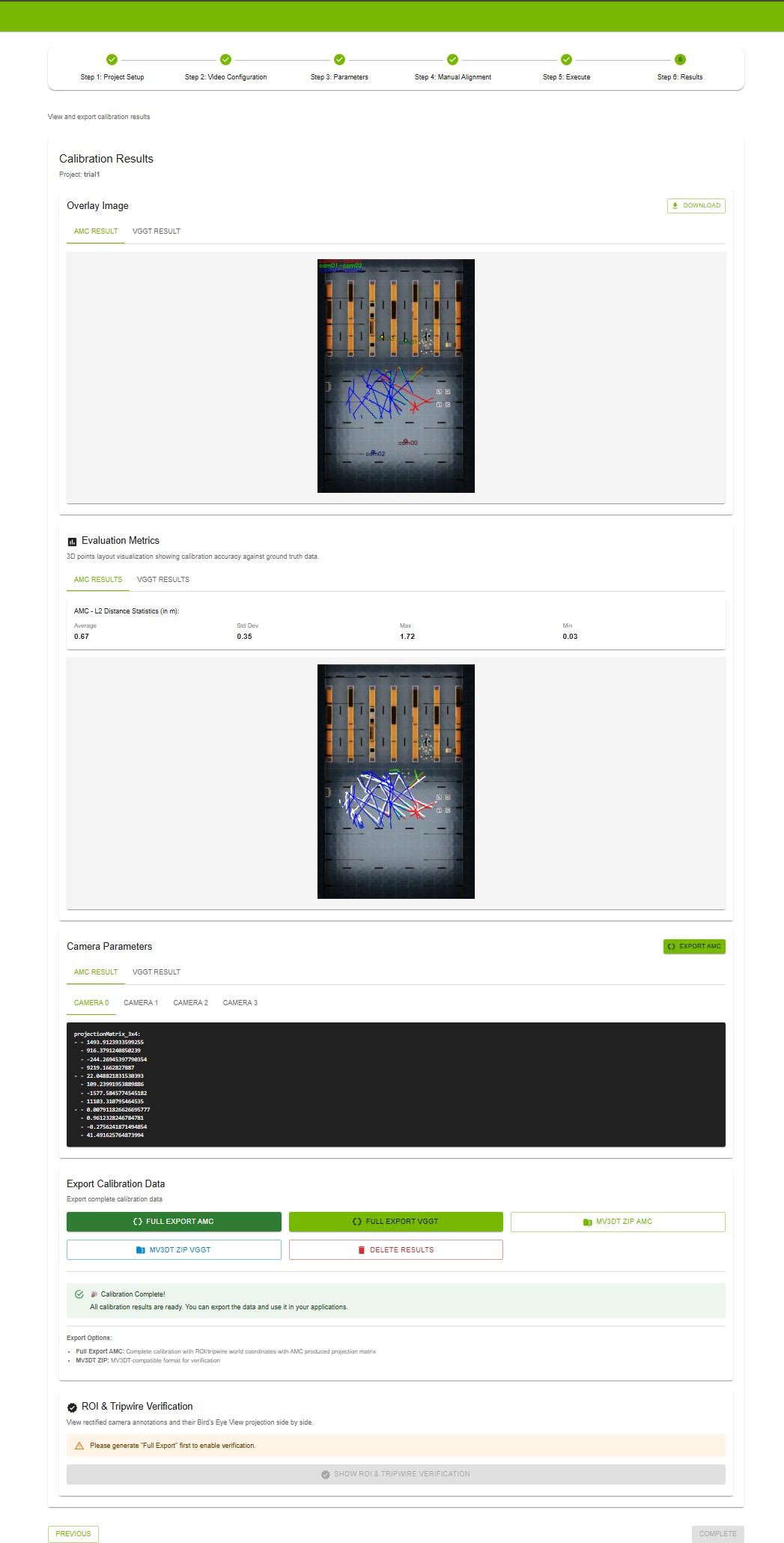
Results Step#
Use Show ROI & Tripwire Verification to project your ROIs and tripwires onto the layout (bird’s-eye view) and confirm they align correctly with the calibrated camera views.
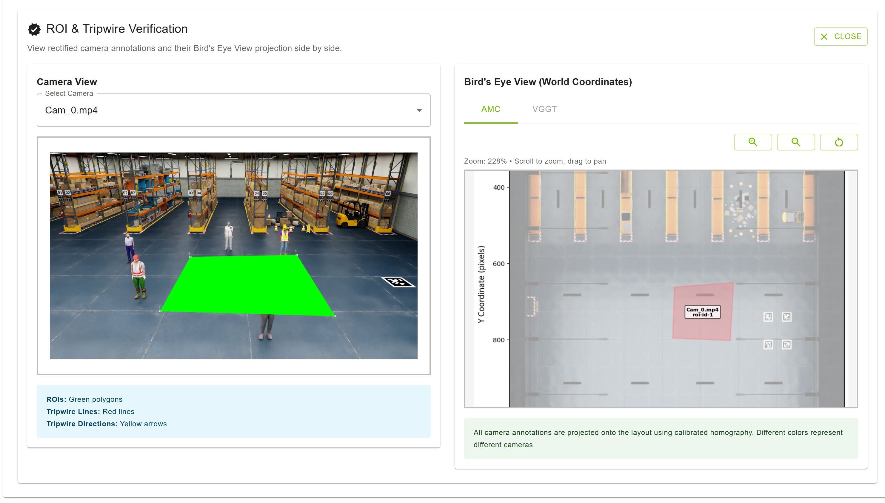
ROI & Tripwire Verification#
Custom Dataset#
Prepare:
Input videos — Camera video files; upload order defines camera pairing; consecutive cameras should have overlapping FOV.
Floor map — Layout/map image of the surveillance area.
Ground truth (optional) — For evaluation, a ZIP containing
calibration.jsonandground_truth.json.
calibration.json — Sensors array; each has id, intrinsicMatrix (3x3), extrinsicMatrix (3x4), cameraMatrix (3x4), attributes (e.g. frameWidth, frameHeight). Matrices follow OpenCV-style definitions.
ground_truth.json — Frame index as key; each value is an array of objects with object id, object type, object name, 3d location [x,y,z], and 2d bounding box visible (camera id → [x_min, y_min, x_max, y_max]).
Guidelines for Input Videos to Achieve Optimal Calibration Results#
To ensure the most accurate camera calibration, careful consideration should be given to how the input videos are captured. The following points detail how to maximize the quality of the calibration outcome.
1. Minimizing Lens Distortion
The current calibration methodology performs best when input videos are “linear,” meaning they exhibit no lens distortion. While the tool can handle minor distortion, optimal results are achieved when lens distortion is zero.
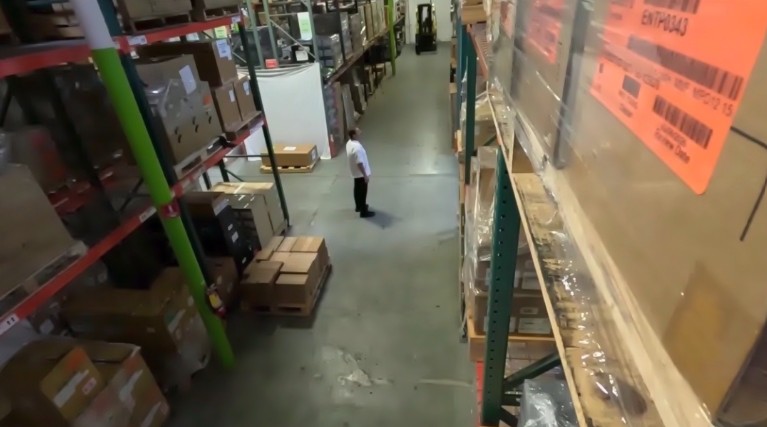
Example of linear video with minimal lens distortion#
2. Maximizing Camera Overlap
Accurate calibration requires a significant degree of overlap between the fields of view of the different cameras. It is essential to maximize the overlap between cameras as much as possible.
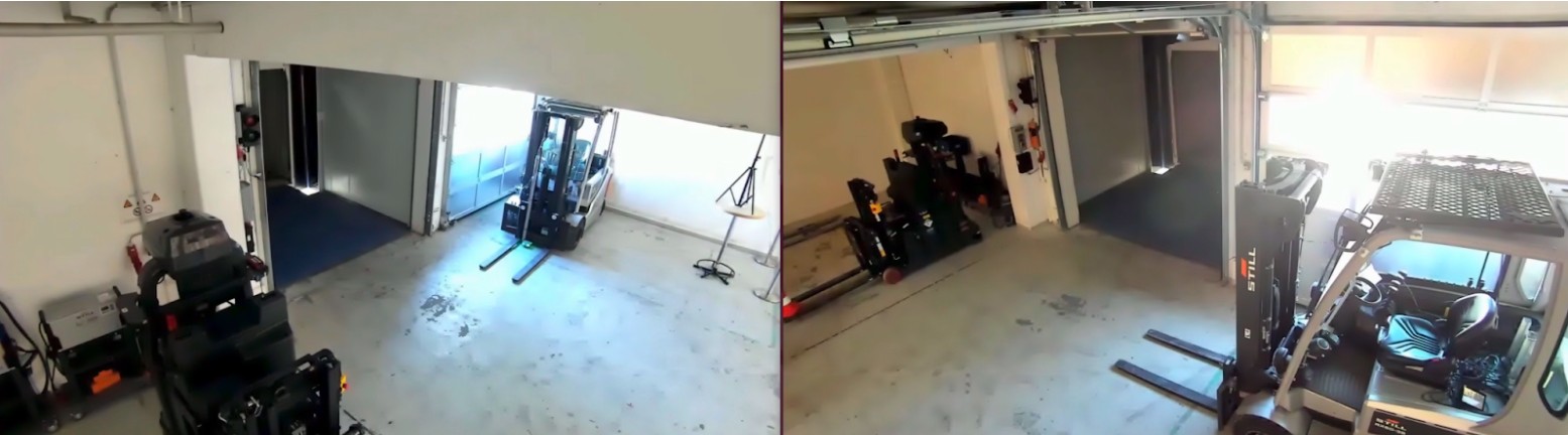
Example of strong overlap between camera fields of view#
3. Leveraging Unique Scene Features
The presence of diverse and unique objects in the input videos contributes significantly to calibration accuracy. The automatic calibration tool specifically utilizes people moving within the field of view, so videos with many moving people are ideal. The trajectories of these moving subjects should cover the Field of View (FOV) as broadly as possible.
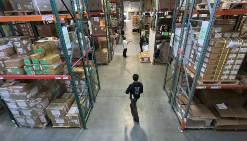
Diverse, unique objects and moving people improve calibration accuracy#
Additionally, large, unique objects can enhance accuracy. For instance, in a setting like a warehouse with multiple cameras, views can become challenging due to repetitive elements (e.g., similar racks). In such environments, large, distinct objects, such as forklifts, are beneficial for better calibration accuracy.
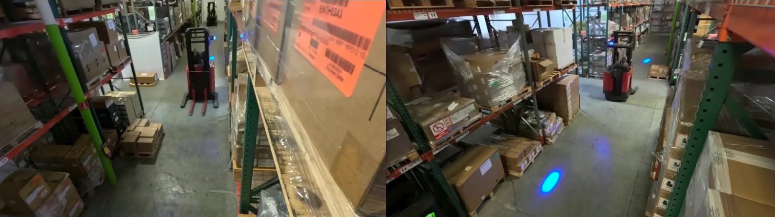
Large distinct objects (e.g., forklifts) in warehouse views aid calibration#
Calibration Output#
After calibration, the UI provides overlay images, evaluation metrics (e.g. L2 distance when ground truth is provided), and per-camera parameters (projection matrix, intrinsics/extrinsics). Export options include full calibration JSON (with ROI/tripwire world coordinates) and MV3DT-compatible ZIP.
Integration with MV3DT#
Export calibration in MV3DT-compatible form from the Results step: use MV3DT ZIP AMC or MV3DT ZIP VGGT. The generated ZIP can be used with Multi-View 3D Tracking (MV3DT) verification tools.
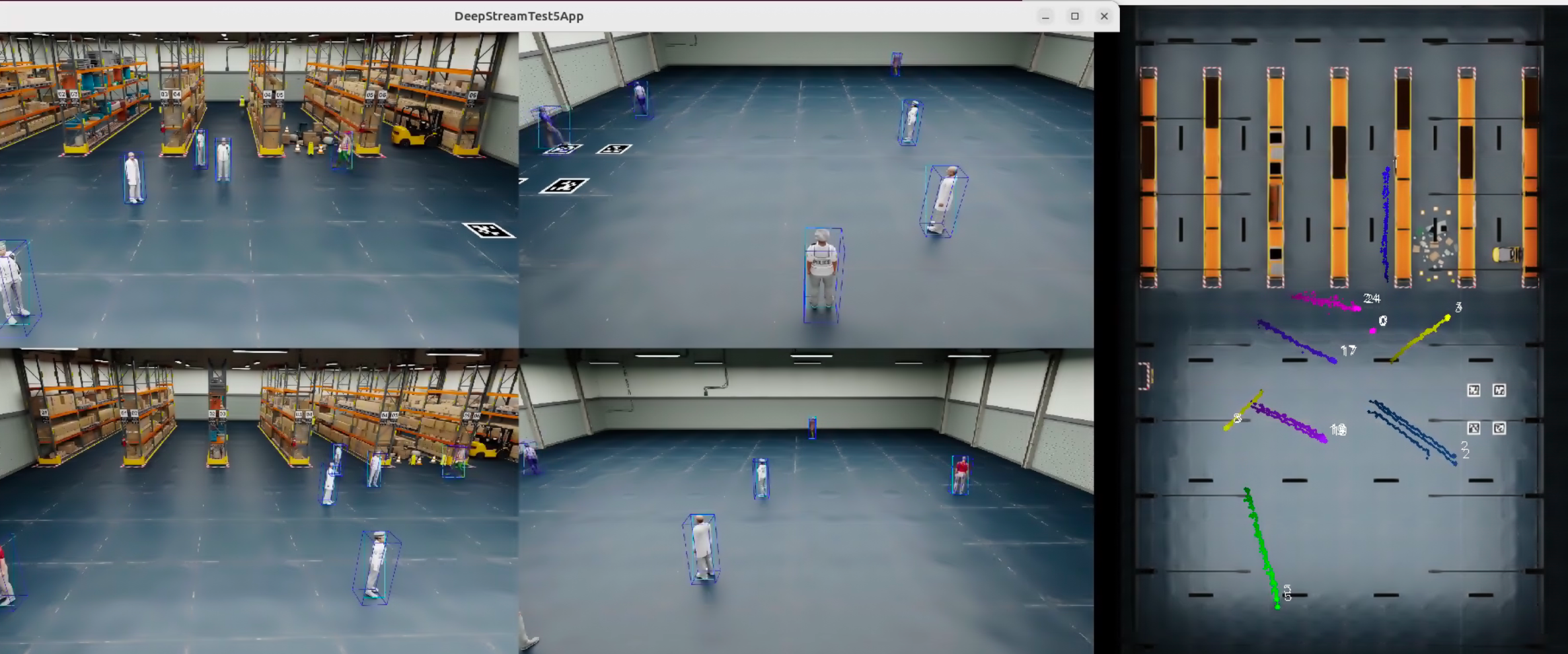
MV3DT real-time multi-view tracking with AMC-generated calibration parameters#
Troubleshooting#
Cannot access UI — Confirm backend and UI are running (e.g. docker ps). Check URL/port, firewall, and connectivity (e.g. ping, telnet <ip> <port>).
Port already in use — Change AUTO_MAGIC_CALIB_MS_PORT and AUTO_MAGIC_CALIB_UI_PORT in compose/.env and restart; or stop the process using the port (e.g. sudo lsof -i :5000).
API_URL_NOT_PROVIDED — Set HOST_IP in compose/.env and restart: docker compose down then docker compose up.
Verification fails — Ensure videos, layout, and alignment (4+ point sets). Check alignment JSON and video integrity; re-upload if needed.
Calibration fails or takes too long — Check input files and alignment (ground plane, visible in all views). Typical run 5–15 minutes. Reset project and retry if needed.
Export or ROI verification issues — Ensure calibration completed. For ROI/tripwire verification, run “Full Export AMC” (and VGGT if used) first.
Additional Resources#
GitHub Repository: AutoMagicCalib for standalone AMC and sample data.
VGGT model: Optional; download from HuggingFace (e.g. VGGT-1B-Commercial) and place in the models directory for VGGT refinement.